System Overview & Documentation
Motivation
Harvey Mudd College includes a plethora of student DJs that perform regularly around the 5Cs. As two currently aspiring DJs, we wanted to understand the technical workings of audio modifications and create a functional deck so that we could perform for our friends.
Insight into how we came up with this project can be found in Victoria’s blog.
Problem Statement
Our overarching goal for this project is to build an operational DJ Mixer that manipulates audio files based on user inputs. Our mixer will be able to control the frequency and gain of audio files passed in via an AUX cord based on physical inputs from the user.
Objectives
The objectives of this project are as follows:
- Use an external ADC to read in a Stereo file into the FPGA
- Communicate audio data between the MCU and FPGA
- Implement low pass and high pass digital filters using the FPGA
- Vary audio volume based on user gain inputs
- Output the manipulated audio onto speakers
We met all of these objectives except for digital filtering. While we had digital filtering working in simulation, we ran out of time to implement it in hardware. As a result, we used the potentiometers in RC and CR circuits to implement the lowpass and highpass filters.
System Overview
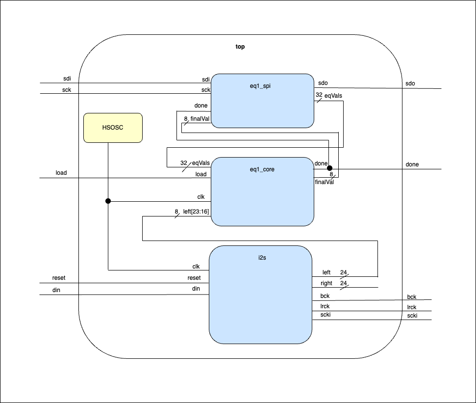
The project is split between the MCU and FPGA. The MCU is in charge of:- Outputing the manipulated audio data with the onboard DAC with DMA
- Interpreting and transferring the user input EQ values to the FPGA
- Acting as the controller for SPI communication
- Generating the Clock for the PCM1808 ADC to read in audio
- Digital filtering of the audio data based on EQ values from the MCU
- Sending audio into the MCU
Ultimately, filtering was handled with an external circuit on the output of the MCU.
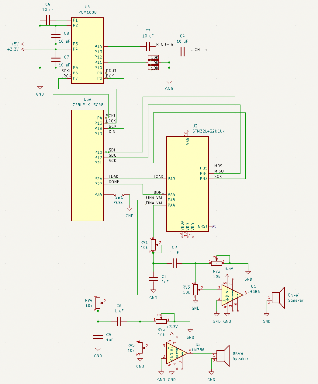
The system is described in the block diagram and wiring diagram below.
Bill of Materials
As our project deals with audio, in addition to the STM32L432KC MCU and UPduino v3.1 with the iCE40 UP5K, we used the following materials. Our new hardware was the PCM1808, an external ADC to convert stereo audio to digital to be read into the FPGA using I2S. More information on the PCM1808 can be found under FPGA & PCM1808 Design.
| Item | Part Number | Quantity | Cost per |
|---|---|---|---|
| PCM1808 ADC Breakout Board | PCM1808 | 1 | 7.99 |
| 10k Slide Potentiometer | PTA2043-2015CPB103-ND | 2 | $1.78 |
| Stereo Headphone Jack | ID: 1699 | 3 | $0.95 |
| Aux Cable | Sourced from stockroom | 3 | n/a |
| 8Ohm 4W Speakers | Sourced from stockroom | 3 | n/a |
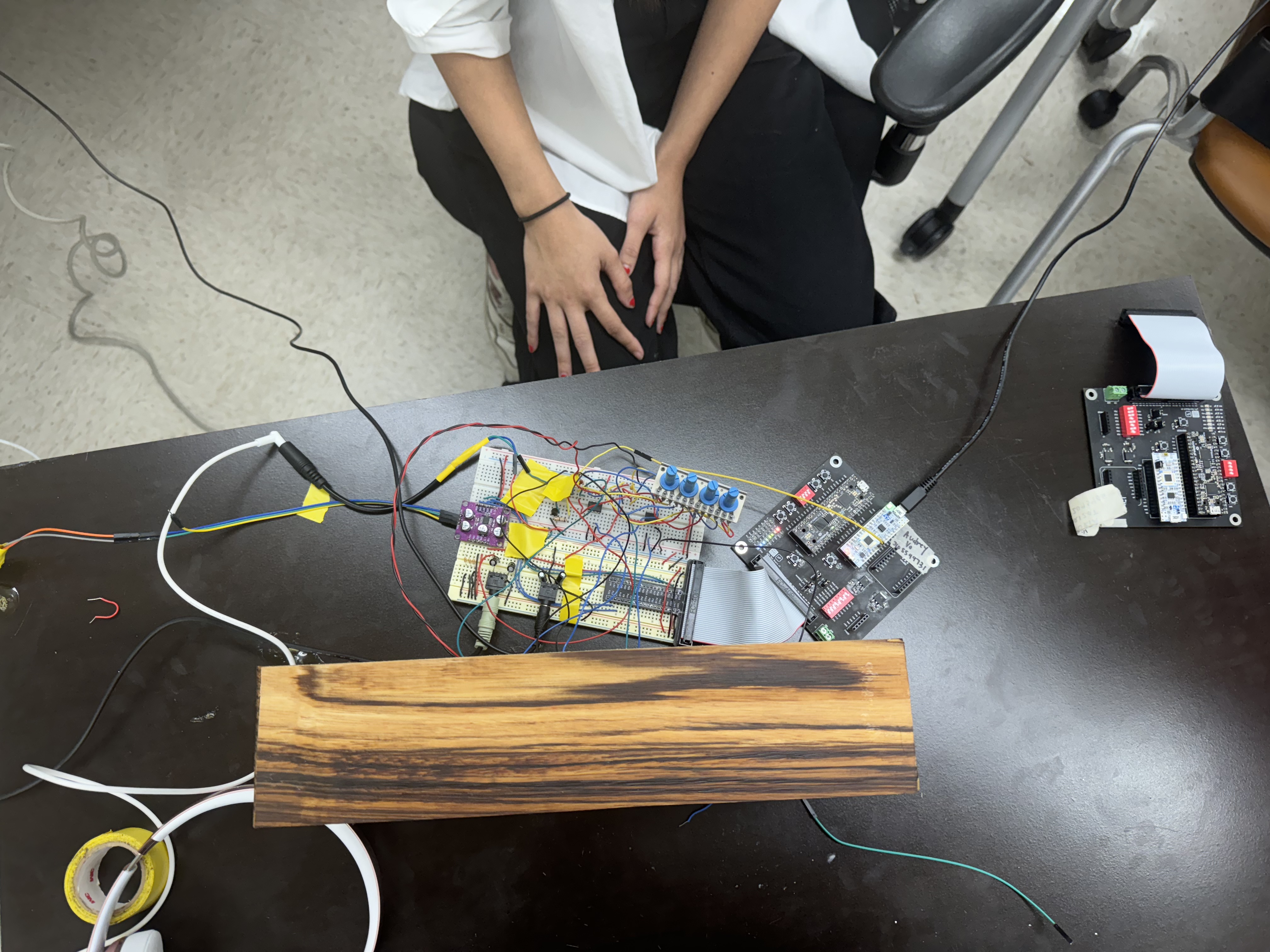
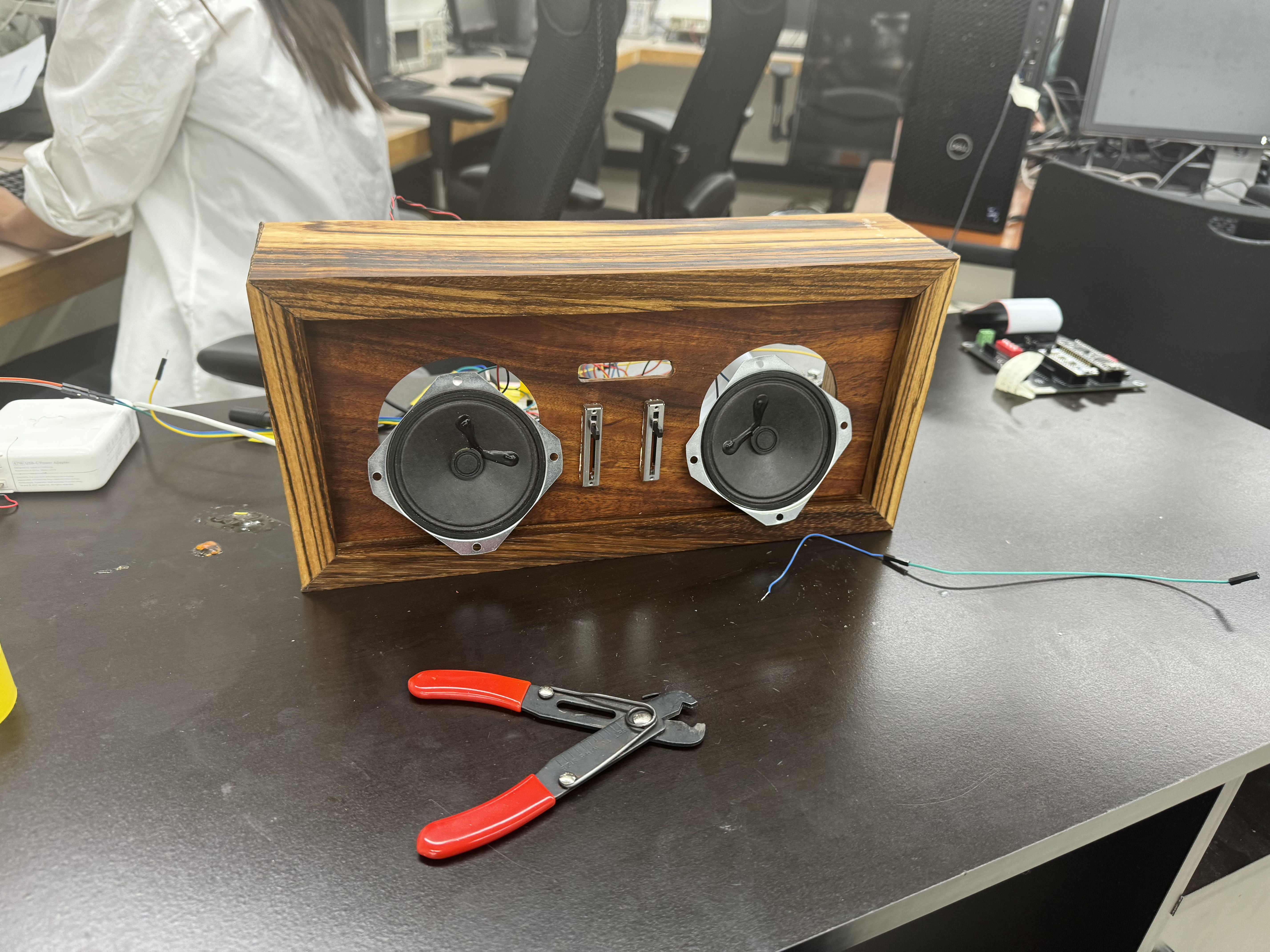
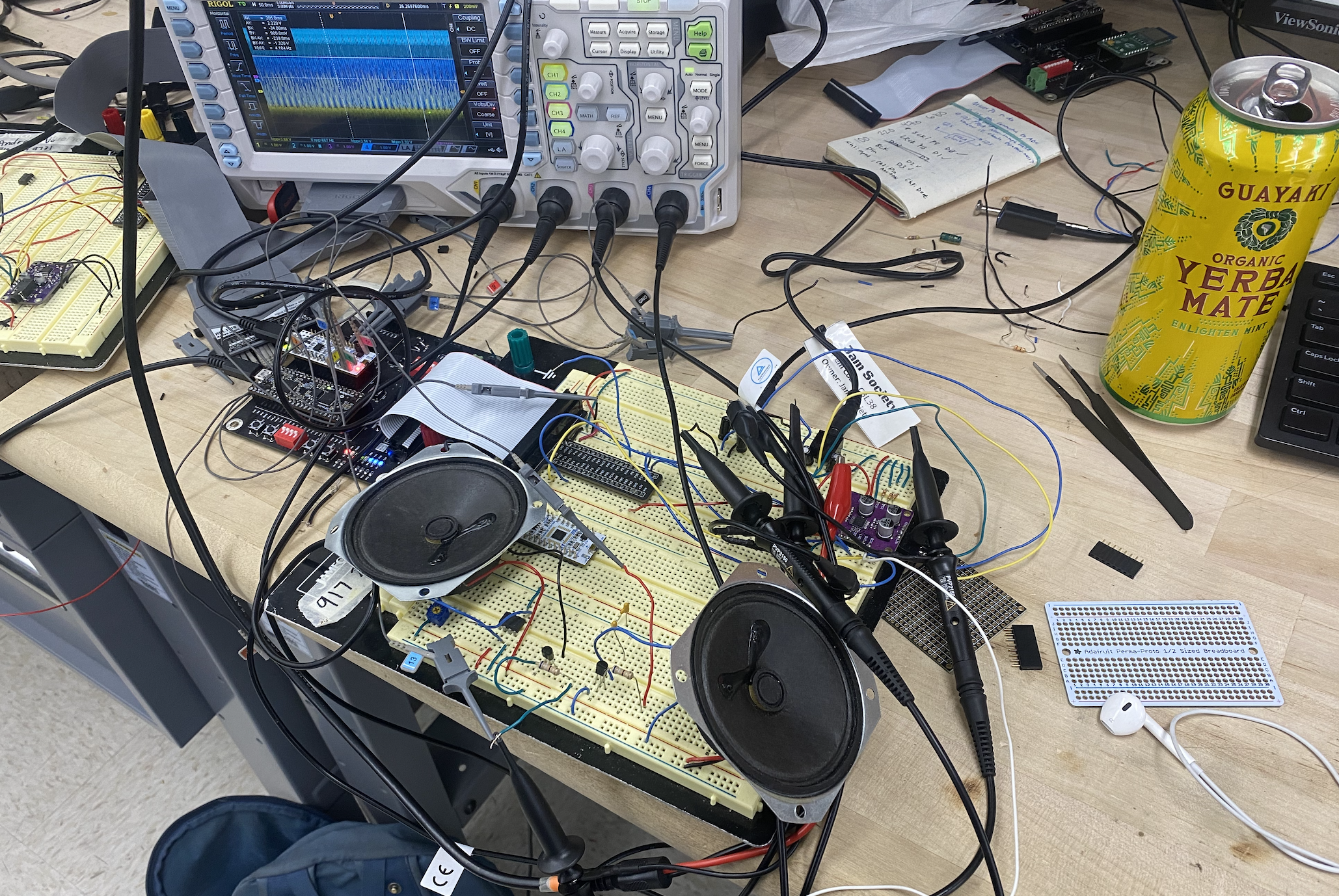
In-Progress Photos
Here are some photos of our design process!
