MCU Design
The microcontroller held three roles in our system. First, it would output the audio, converting it from digital to analog. Second, it would interpret and pass the lowpass and highpass filter cutoff values to the FPGA. Third, it acted as the controller for SPI communication. While we ultimately did not succeed in implementing digital filtering on the FPGA, the MCU fulfilled its role in sending over the filter cutoff values.
Outputting Audio
The MCU takes in 8-bit mono audio data from the FPGA using SPI and stores the value in memory. As the onboard Digital-to-Analog Converter (DAC) can only read positive voltages, we converted our signed values to unsigned values and stored the value into a variable named leftAudio. We then used the onboard MCU DAC with Direct Memory Access (DMA) to convert the digital data to an analog signal. The DMA transfer was initiated by a reload event of TIM7 and would move the value stored in leftAudio into the output register of the DAC. By setting DMA to circular mode, it would continuously read from the leftAudio variable, as it was updated by SPI. Therefore, it was imperative to ensure that the clock speed of both the FPGA and MCU would be fast enough as to not warp the audio.
To make our code scalable to stereo audio, we used both DAC1 and DAC2 and their corresponding DMA channels to output the audio to two separate pins, PA4 and PA5. This also allowed us the flexibility to manipulate the output analog audio with circuits to apply lowpass and highpass filters.
When we opted to use the onboard MCU DAC and SPI, we were hesitant of bringing down the audio data from 24-bit to 8-bit resolution, which would mean lowering the discrete levels of audio from 16,777,215 to 256. While this would not impact the maximum amplitude, it would reduce the precision and dynamic range. We decided the best way to test this would be by doing – so we implemented the DAC and DMA with 8-bit resolution and tried to see if we could spot an audible difference. When testing with sine waves at different frequencies as well as our personal playlists, we could not tell the difference between the original audio versus the MCU output audio. Therefore, we decided that 8-bit audio would be sufficient for this project.
Filter Cutoff Values
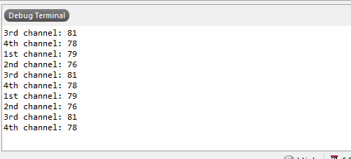
The EQ values are determined by potentiometer voltage dividers being routed into the MCU. The MCU ADC converts these analog values into 8-bit values between 0 to 256, which will ultimately be used to determine the passband frequencies for the low and high pass filters.
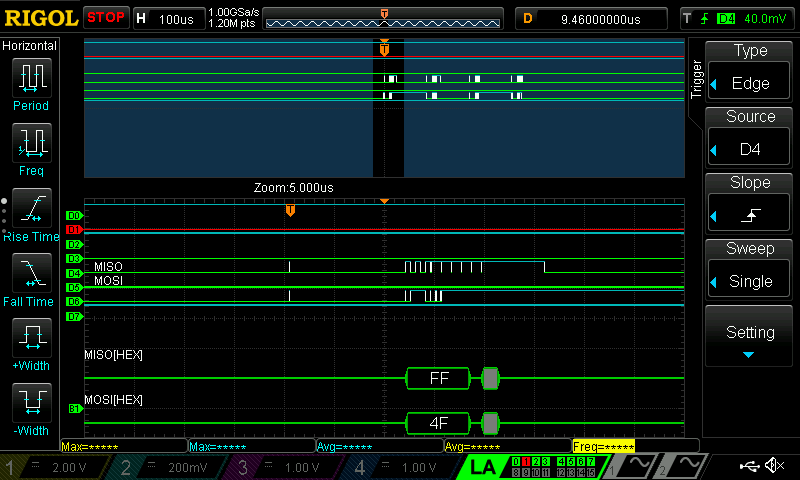
After the MCU interprets these voltages into 8-bit values, it passes these values using SPI to the FPGA. Below is an example of a working SPI interaction. When the potentiometer is set to approximately 79.


SPI Controller
The MCU generated the SPI clock and took charge of sending and recieving the potentiometer and audio data packets by using a load and done flag. Where the load flag would be triggered after the MCU has sent the potentionmeter values and the Done flag would be triggered after the FPGA has finished processing an audio packet.