Hardware Design
Hardware Design
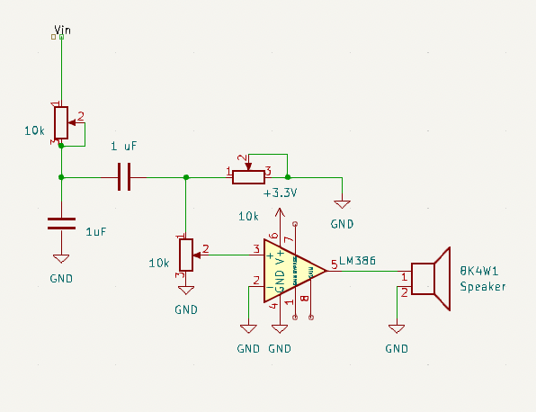
Because digital filtering was not implemented on the FPGA, an analog circuit was used instead to control the filtering of the outputted digital audio and the gains of the audio. An RC circuit (low pass filter) was put in series with a CR circuit (high pass filter) to create an overall bandpass filter. The resistors of the RC and CR are 10k potentiometers, while the C value is 1 uF to allow for a cutoff frequency between 15 Hz and 32000 Hz. This is a reasonable range since human hearing goes up to 22000 Hz.
Calculations to Determine the Needed Capacitance of Circuit
\[ \text{Cutoff Frequency for RC/CR filter} = \frac{1}{2\pi rc} \]
\[ \text{Potentiometer Range} = 5 Hz to 10 kHz \]
\[ f_c = \frac{1}{2\pi rc} = \frac{1}{2\pi (10000)(1uF)} = 15.92 Hz \]
\[ f_c = \frac{1}{2\pi rc} = \frac{1}{2\pi (5)(1uF)} = 31,831 Hz \]

The output of this bandpass filter was then inputted to another set of sliding 10k potentiometers to control the gain/volume of the audio. An LM386N audio amplifier was then used to connect the output of the gain potentiometers with an 8K speaker because the MCU pins did not generate enough current to drive the speaker.